Main Page › Forums › L-5 Restoration Forum › WTB Battery Box
- This topic has 18 replies, 3 voices, and was last updated 2 years, 3 months ago by
admin.
-
AuthorPosts
-
-
2024-01-28 at 7:54 pm #6509
G’day Team,
When I purchased VH-BFR it didn’t have a bettery box, the battery just sat in the cradle held down by what looked like an automotive clamp. We are planning on fitting an Oddessy which we think should fit without any problems. So we either buy one or we make it.
My question is: does anyone have a battery box suitable for the L-5 they are able to offer up for sale?
Hilly
-
2024-01-29 at 8:52 am #6510
Geoff: I ran thru the IPB and it appears that there never was a battery box for the L-5. It shows that the battery was held in place by the tabs around the shelf it sat on, combined with a cross bar type hold down.
-
2024-01-29 at 12:29 pm #6511
A battery box should certainly be used, particularly for a lead-acid battery so the fumes can be contained and vented overboard, which is part of the original design and therefore a mandatory airworthiness requirement. Even for other types of batteries, such as gel cells it’s a very good idea to keep them contained. I’ve seen those plunked in there on a piece of board and held down with zip ties, believe it or not.
There is a battery box drawing in the L-5 blueprint set, but alas it was for the prototype Model 76 and it’s way too tall for the production aircraft. It could be used as a starting point for designing a custom box though, but several changes would have to be made.
None of the commercially available boxes that I have seen are ideal and very few will fit in the rack properly; most being too big in at least one dimension. As far as I know, Odyssey only makes two suitable batteries that fit within the rack, so you might have to build a custom box for it. I prefer side posts and also don’t like the SAE top post design of the Odyssey batteries that will fit (at least those sold in the US).
For a bang-on authentic-looking restoration the ideal setup is to find the carcass of a vintage AAF battery, gut it, and use the casing as the battery box, which some modern batteries will fit inside. Several people have done that .
Example:
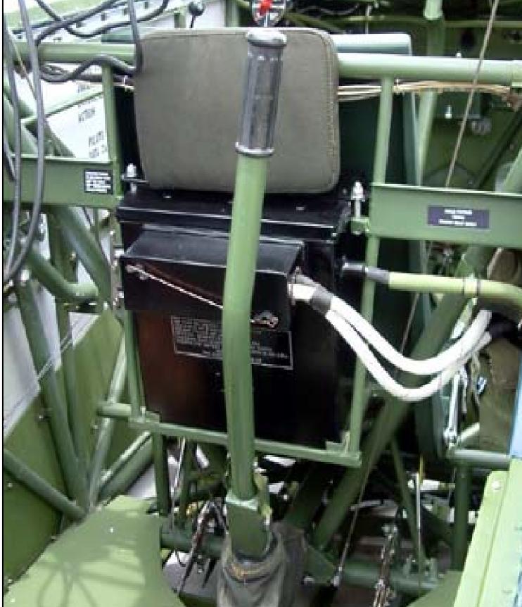
I have seen (and owned) several L-5 battery boxes that were either of military manufacture (probably Navy), or provided by a contractor in the late 1940’s or 1950’s . These have lids with tabs that work with the hold down lugs in the aircraft and were made to fit the L-5 battery rack. I have at least one of those that I’ll be happy to photograph for you when I’m next at my hangar. I used t have one from a Stinson 108 that worked okay, but it required a bit of modification.
Custom building a box is usually the best option, which is probably not what you wanted to hear. I shouldn’t assume that your battery rack hasn’t been modified because that might dictate what you’re able to use.
-
This reply was modified 2 years, 5 months ago by
-
This reply was modified 2 years, 5 months ago by
-
2024-01-29 at 2:37 pm #6513
Morning Team,
Graig, many thanks for your comments. I had looked at the IPC which is probably why VH-BFR was set up like that in the first place, I wonder how many other L-5s are flying around like that.
I won’t repeat all of the great advice regarding the use of battery boxes from JG, he has nailed my thoughts exactly. I recently found a suitable NOS battery (never had acid added) on an FB market place, made the offer (which was accepted) but the seller must have found a local buyer local because the advert and corrospondence suddenly ended. JG’s photo is exactly what I am after…. if I can find one.
Jim, as you have said; I will probably have to make one. In the mean time I will continue to look, if I don’t ask then I won’t get and if I do ask then I run the risk of success.
Hilly
-
2024-01-30 at 7:22 am #6514
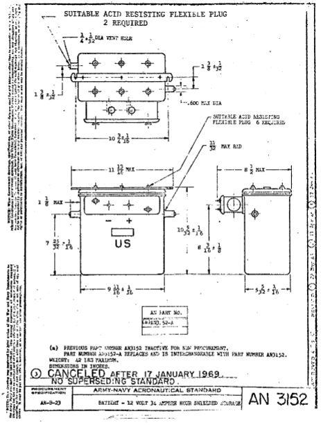
Did a little cracking of the books this morning and discovered that the AN3152 battery was also used in the OA-10 Catalina. The 3152 is apparently steel cased, with a gasketed lid and provisions for vapor venting and drainage. Electrical terminals are also cased, so no box needed. I think I found a source for the spec, but will have to try tomorrow on gaining access.
Craig
-
2024-01-30 at 11:16 am #6515
Craig, I believed that Taylor used one of those batteries as a battery box for his G-model if you want to eyeball one in person. One of the reasons they make such a good battery box is the built in venting and drain.
-
2024-01-31 at 1:22 am #6516
Yesterday, someone (cvairwerks) on another forum (G503.c0m) had the same idea. There is no evidence that he has had any replies yet but clearly we are all in furious agreement. Is that you Craig??
-
2024-01-31 at 6:29 am #6517
Geoff: Yep, that’s me. I also added the question over on WIX as well. Jim mentioned Taylor doing one for his G model, but the G’s used a completely different sized battery than all the others.
-
2024-02-29 at 10:41 am #6524
A friend that works for a different aerospace company from me, came up with a copy of the AN3152 battery. Holy smackers it’s small for what all it powers. Basically it’s 5″x 9″x 11″ tall.
-
2024-03-01 at 10:42 pm #6525
Cool Craig,
When I look at the AirCorps library drawings I find 76-64003 BOX – BATTERY EXIDE 12 VOLT with internal dimensions of 10 7/16″ long x 5 7/16″ wide and 12″ high which has a lid. Dimensions from your mate are pretty close.
There is also a drawing 76-64303 SHELF – BATTERY which seems pretty basic and has holes to match 76-35038 SHELF ASSEM – BATTERY. The dimenions look a bit odd to my eyes in that it is too short and too wide for a neat fit of the battery box. That said I could be reading the drawings incorrectly.
Finally drawings 76-64304 BATTERY HOLD DOWN STUDS (which look like a simple rod threaded at both ends), 76-64336 TUBE – BATTERY INTAKE and 76-64339 TUBE – BATTERY DRAIN (self-explanatory).
When I compare the photo kindly provided by JG, I wonder if the L-5 & L-5B installations were different. Only drawings for a single install so not sure that is right either.
Many thanks for your help Craig, next time I am at the aircraft -maybe a month or so – I will take to the current mount to measure and compare.
-
2024-03-01 at 11:52 pm #6527
Hilly … look closer at the title blocks of those drawings. 76-64003 is for aircraft 9001 which was NX27772, the L-5 prototype. To my knowledge, that battery box was not used on any production aircraft. All of the other drawings pertain to the 24-volt L-5G (76-3477 & up). The devil is in the details, as they say. A large number of drawings in the set (which are available FREE to level 3 and 4 SOPA members) are prototype or experimental designs only and do not pertain to doing an authentic restoration on any of the production airplanes.
-
2024-03-02 at 6:20 pm #6532
Geez Jim, now I feel so thick!! You will have to help me out here mate, while I guess the quality of some of the drawings is pretty ordinary. when I look at some of the drawings they say L-5 not L5G.
All that said, there is still so much I have to learn.
So, is there any information for battery installations post these drawings, particularly the AN3152?
-
2024-03-03 at 8:27 am #6533
Hilly,
Not only are drawings 64303, 64304, 64336, and 64339 for the L-5G as marked, but so is 35038. Although it says “L-5” in the title block, it should say L-5G instead. Being intimately familiar with that model because I own one that is disassembled, used to own the frame of another, and have laid eyes on several more, I instantly recognized that this is the assembly welded to the fuselage tubing at the firewall, where the 24-volt battery is located. On all of the 12-volt models, the battery shelf located behind the front seat has different dimensions and has different support tubing associated with it.
A few details in that blueprint are also clues that it is a late-model part. The title block indicates that the drawing was created on 2 March 1945 and was approved by the Chief Engineer and Project Engineer on April 4, and the note next to the title block says that 76-35038 replaces 76-31164. Even though the drawing for the earlier part isn’t in the blueprint set, it can only have been the earlier welded battery shelf assembly used on the 12-volt airplanes, especially because the L-5E series started rolling off the assembly line in February 1945 before the drawing 35038 was made.
That isn’t a fact generally known, however, so I have an advantage over you and most other L-5 enthusiasts there, but the clincher is that the “Model No” referred to in the title block is CS-91 which is an engineering reference to the ‘G’ model. Like serial number 9001 being the Model 76 prototype for the L-5, this extremely obscure bit of trivia isn’t something that I would expect anyone else to know, and I only sussed it after poring over hundreds of drawings and stumbling across a few that spell it out plainly. Anyway, while I have looked at it many times before, until now I never noticed “L-5” or “CS-91” on drawing 76-35038 because it was already plain to me that it is the G-model battery shelf and I had no reason to look deeper until you posted your question about it.
To answer your other question about AN3152 and any other drawings concerning battery installation, there aren’t any in the NASM blueprint set that we can refer to because most of the superseded drawings were deleted. However, back in 2013, I filed a Freedom of Information Act request with the FAA to gain access to their engineering data and in 2014 had the rare privilege of rummaging through their collection of L-5 documentation for three days. This included several boxes stuffed with original blueprints that probably hadn’t been touched since 1946, and among the collection were many “missing” drawings of superseded parts. Duncan Cameron went along on this expedition and here is a photo of him holding the first drawing that we randomly selected from the box. His grin says it all – jackpot!
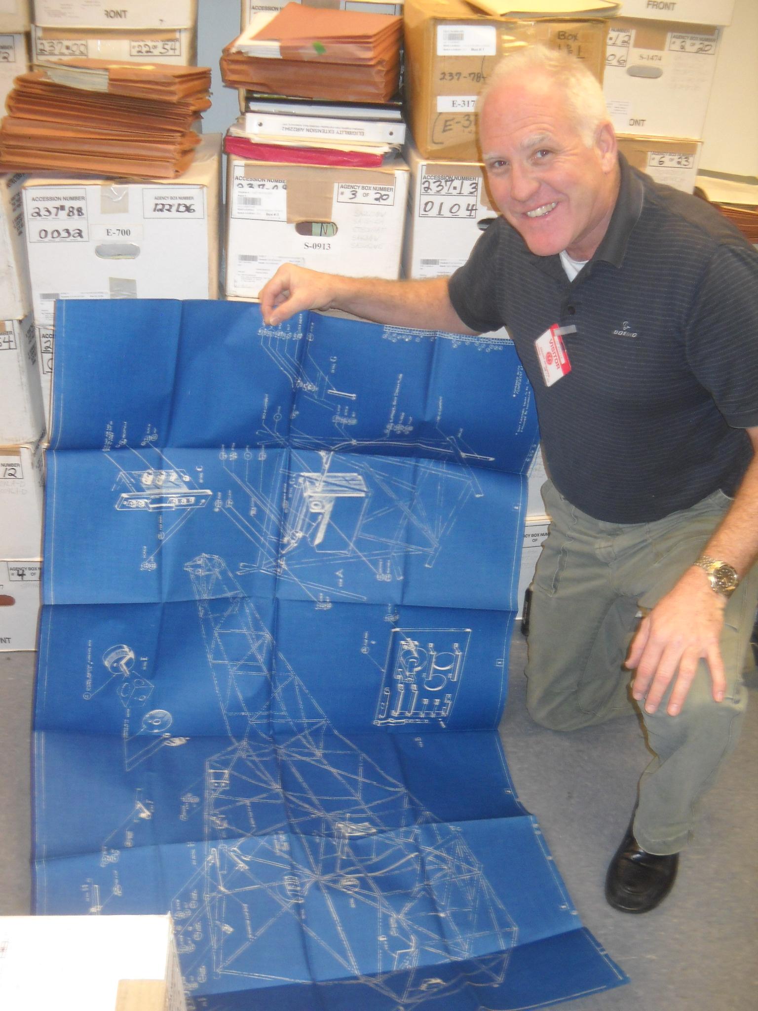
Unfortunately, we found no other drawings concerning battery installation, but this one has some very useful details on it. It is actually for the early L-5, the so-called O-62 batch of planes numbered 76-1 to 76-275, but most items are the same as on later models except for the radio equipment, some of the wiring harness details, and a bit of the bracketry. A smaller version of this blueprint is also probably included in one of the many versions of the L-5 parts catalog, but my set of those is not accessible at the moment, and none of the manuals on the ACA website have it.
My copy of the drawing shown in the photo has been lost, unfortunately so I’ll have to ask Dunc to send me his copy which I will forward to you if you provide two bars of platinum bullion, a bouquet for my wife, and the deed to your farm in Oz (hahaha).
Cheers,
JG
-
2024-03-03 at 9:51 am #6534
Hilly: Something that will help you immensely on chasing applicable drawings is to pull the part number from the IPB, then apply the effectivity markings and then go to the drawings.
A quick and easy example;
Go to the page on lift struts in the IPB. If you look at the first set of entries, you will find three part numbers there for the A model. 76-10001-0, 76-10001-1 and 76-10060. Looking to the left of the part number, you will see that there is a cross symbol on all three part numbers and a 2 in front of the cross on 76-10060. Down at the bottom of the page, there is a list of the cross and the number 2, showing what aircraft that part number is effective for. In the case of s/n’s 42-14798 thru 42-99160, the 76-10001 series parts were the original install, and the 76-10060 was used on 42-99160 and on. As the cross is applied to the 76-10060, in means that should one need to replace a lift strut on the early model, the later version of the strut is an acceptable direct replacement.
Where things get complicated, is when there are multiple part numbers and installations and optional configurations. I’ve had some drawings at work, that have as many as 100 effectivity flags to show what airplane gets that particular configuration…..
-
2024-03-03 at 9:55 am #6535
Forgot to add, here’s the spec on the battery:
-
2024-03-03 at 10:16 am #6537
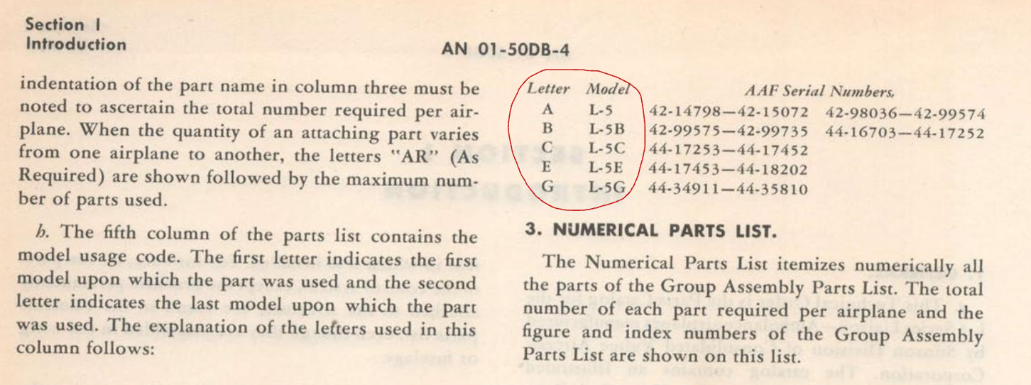
Correction Craig: There wasn’t an “A model”. Although the “observer” model is often referred to as the L-5A, that was not an official designation. In addition to what can be derived from the maintenance manuals, I have thousands of pages of Wright Field documentation on the L-5 program and it provides incontrovertible proof that the L-5A never existed, despite what commercial publications such as Jane’s All the Worlds Aircraft have published for the past 70 years. It was designated as an L-5 throughout production until the L-5B ambulance version was introduced. If you look at the chart below from the Introduction section of a late edition of the Parts Catalog, it is quite clear:
-
This reply was modified 2 years, 4 months ago by
-
This reply was modified 2 years, 4 months ago by
-
2024-03-03 at 9:01 pm #6538
Many thanks for your kind assistance, wise advice and guidance Craig.
If I may ask one more favour from you please: can you email the image of the battery specs to me (can’t copy, transfer or print from this platform). Please use: grhilly@ozemail.com.au
Jim, happy to provide a bouquet for the missus and if you want the deed to any farm I own, then it’s yours (no farms here mate….that I know of). I will file away the obscure information as you have enlightened us , all good info and part of the learning mate.
To you both, I am grateful for the time you have taken and guidance provided and I have enjoiyed this discussion. All of this, I think, should be shared with others as well.
Both of you have so much information filed away in your heads I wonder if there is an opportunity to share with other L-5 owners & operators separated by the tyranny of distance. Maybe via webinars, blogs, vlogs, youtubes or any other modern electronic means. Maybe we can have a regular online vidcons and include a scripted lesson.
I have looked back over this conversation and think about the time and effort we have put in. As they say in the classics: there is no tone or intent in short messaging and it’;s so time consuming. Some of your really good information & lessons can be delivered with so much more power and purpose.
If all else fails I prefer a phone call or online video messenging.
Many thanks guys.
Hilly
-
2024-03-18 at 10:21 am #6543
Jim: A side question about your trip to the FAA archives….Did you have to supply your own copying equipment, or did the FAA people do it for you? How rough was the cost at the time… per page or drawing or by whatever was in the complete box?
I’d like to get into the files for a particular TC from the 20’s/30’s and see if some unlocatable drawings are within the TC files or not.
-
2024-03-18 at 1:06 pm #6544
Craig,
The FAA Engineering Office (ACO) in Chicago has a small staff and they aren’t set up to handle visitors who do research. They have no copying equipment for visitor use and nothing can be taken off-site for professional copying, although they did photocopy some reports for me on one of their copiers (I don’t recall the fee). Any equipment brought to their office other than a small flatbed scanner or camera must be approved beforehand, and everything entering and leaving the building is screened by security.
Because very little would fit on my 10×14 “legal size” scanner, I photographed most items instead. Given the age and fragility of the heavily-creased drawings larger than ANSI ‘A’ size, it was impossible to flatten them without risking damage. According to my archivist-wife, the only practical way to handle and copy them properly would require a lot of time for controlled humidification of the paper (allowing the creases to relax) and some very expensive ($50k+) large format scanning equipment.
To accommodate us during our visit, the ACO staff cleared off a desk in a dingy 12′ x 20′ basement storage room that was piled with boxes and broken / unused equipment, so there wasn’t much room to work. They did make a conference room with large tables available to us for most of one day so that we had room to unfold the large drawings, but we were required to have an escort to walk between the rooms on separate floors, which was inconvenient for us and the ACO staff.
All of the records are warehoused off-site, so getting the boxes ordered took time and needed coordination with our schedule and their schedule. Because the files weren’t very well indexed, I had them pull something like 20 file boxes containing “orphan-status” Stinson material to be sure that I had covered everything date-wise from 1940 onward. Only six of the boxes held pertinent information, (which I thoroughly indexed for the ACO to aid future researchers) but it was better to cast a wide net to be sure that we didn’t miss anything.
Although it should be obvious, I should mention that there is no public access to currently supported TC and STC engineering data, no matter how old it is. There is no statute of limitations on proprietary aircraft design and engineering information, so before honoring any request for a research visit the ACO has to go through the time-consuming process of determining whether the type certificate holder of record still exists or has sold/transferred the rights to a new owner. That alone can take months if it hasn’t already been established, and in my case back in 2012, it took over a year because no one had previously requested engineering data and drawings for the L-5. Unless the ACO has formally declared which aircraft are “orphans” since that time, you can probably expect a similar delay with whatever “20’s/30’s” aircraft it is that you are referring to.
Good luck,
JG
-
-
AuthorPosts
- You must be logged in to reply to this topic.