Main Page › Forums › L-5 Maintenance Forum › Tail wheel cable tension
Tagged: Tailwheel
- This topic has 10 replies, 3 voices, and was last updated 4 years, 8 months ago by
 Matt Anderson.
-
AuthorPosts
-
-
2022-01-24 at 6:16 pm #4733
I was rigging the control cables for the rudder and tail wheel the past weekend. With the tail wheel off the ground I set the rudder tension to 70 to 75 lbs per the manual. Then I tensioned the tail wheel cables to 10 lbs then backed off to 0 lbs so that I took out as much slack as possible while still setting at 0 lbs per the manual. The 1944 maintenance manual incorrectly states the tail wheel tension when on the ground is 70 to 75 lbs. This statement is deleted in the 1956 maintenance manual. The tail wheel cables still feel slack when on the ground. My question is there anything else I need to do to know they are correctly adjusted?
Thanks in advance
Matt Anderson
-
2022-01-25 at 7:48 am #4738
Hi Matt, You hit on a good subject. The manuals are poor covering this area. The tension values should be measured with tail off the ground. (Note #8 of rigging info chart on page 2A of July 1953 manual revision). The best way to approach this is to view the systems as two different entities. Steering cable system and Rudder cable system.
The tail steering cables (with stock Lake State tail gear assy installed) was rigged with tail off the ground, tail gear fully drooped. There was no tension to the cables, just all slack removed. I tighten the turnbuckle until the spring just moves (stretches about the width of a piece of paper). Adjusted this way and tail gear off the ground there is no steering cable tension force being applied to the rudder cable system at this time.
Because the steering cables travel <span style=”text-decoration: underline;”>under</span> the cross tube of the drag link (the cross tube is the pivot center of the tail gear drag link assy.) this mean the the cables and the drag link have different pivot points. As the tail gear moves up (weight on the plane) the steering cables will get tighter the farther up the gear moves. (Read that let sentence again:)
<span style=”text-decoration: underline;”>Side note</span>: the original L-5 tail steering cable springs were “Compression” type springs. This means that as the spring assy is pulled by the cables, the actual spring portion will be squeezed (compressed). There is a limit to its travel. When it is pulled to full limit, the compression spring will squeeze and hit “Coil bind” meaning the spring assy stops stretching. Tension springs, however, will just keep stretching with no hard limit.
Sorry back to cables…. The rudder system is a closed loop system. This design means the rudder pedals, rudder arm are all connected and under cable tension the entire time. A small cable runs from the front Left Rudder pedal forward toward the firewall through 2 pulleys and back to the Right Rudder pedal. This is the balance cable and it completes the “loop” at the front end. (the rudder arms completes the “loop” at the back end).That Rudder cable “Loop” is to be tensioned at 70-75 lbs. in static mode, which is quite high compared with most planes of that era (and I don’t know why).
With tail gear off the ground, if you installed a cable tensiometer on the balance cable and one on the rudder cable between the front and rear pedals, in static mode, they would each be 70-75 lbs. If you get in the the plane and place your feet on the front pedals and applied the brakes (which loads the rudder pedals forward) you would see a decrease in balance cable tension and an increase in the cable tension aft of the rudder pedals. You are loading the rear part of the loop and unloading the front part of the loop by pushing on the both pedals forward at the same time. In other words, cable tensions on systems will fluctuate as the are being used. But in static mode, all tensions are stable.
Now, take your properly tensioned rudder loop system and set the tail on the ground. The tail steering cables have gotten tighter (normal). This will “pull” aft on the rudder cable system at the rear rudder pedals where the steering cables attach to the rudder cable system. That means it pulls on the front end of the loop and unloads the rear part somewhat. That throws off proper tension readings (with tail on the ground) .
I get asked ,what is the proper tail steering cable tension on the ground? You cannot say because there are so many variables. Spring tension strength, tail gear deflection, weight of the tail at the gear, rudder cable system tension, spring type all effect it.
So Matt, your answer is remove slack on tail steering cables with tail off the ground. Like you did.:)
The extreme check is make sure the springs will not coil bind with the tail heavily loaded. Get some people to push down on the Horz Stab Front Spar ( NOT the leading edge!) and compress the tail shock spring as far as you can and make sure the spring does not bottom out(coil bind). The steering cable tension is what it is.
Hope this make sense:)
Sam T
Hey Jim , You may want to do your magic and put this the maintenance forum too.
-
2022-01-25 at 5:15 pm #4828
Thanks for the response. I noted that you mentioned the tail wheel needs to be fully extended. After I replaced all the seals and serviced the strut the tail wheel does not extend automatically so I will need to pull it down to the fully extended position and take out more of the slack in the tail wheel cables.
Matt Anderson
-
2022-01-25 at 5:50 pm #4830
Matt,
So, you’re happy with the tailwheel oleo not fully extending after you rebuilt it? How far does it extend? Just curious.
Also, how does it sit at rest with 200# in the front seat and the equivalent of full fuel in the tanks, and then when you’ve added 200# to the rear seat and 50# on the rear platform, simulating aft CG? My point in asking is that the tailwheel pivot post should have a positive caster angle to it (i.e. the top end should point slightly aft of vertical), otherwise you could end up with tailwheel shimmy which will get worse when the aerodynamic force of up-elevator is added. I’m just trying to think ahead for you if you haven’t considered that yet.
Lastly, we (as in various other club members and I) have found rudder cables installed wrong-end-forward, as well as cables of the wrong length installed, and left swapped with right, and wrong-sized tailwheel springs. Those situations can frustrate your rigging attempts so it’s worth the extra checks before you set the tension.
Jim
-
2022-01-25 at 7:38 pm #4889
When the strut has little to no fluid in it it will drop to its full length which is longer than the strut spring. With good O-rings and properly serviced with fluid, the strut on its own will only extend to the length of the spring in its uncompressed state. I can pull the tail wheel down further, which would extend the strut past the strut spring length and allow me to take out more slack in the tail wheel cable while maintaining O# tension on the cables with tail wheel off the ground. If someone knows the correct length of the strut spring I can check that and confirm that is not an issue. The tail wheel pivot post does have positive caster while on the ground. I did measure the cables to confirm correct length and installed in correct direction. Cable springs match original Stinson drawings.
-
2022-01-25 at 8:01 pm #4893
Blueprint 76-42036 says …
Free length of the spring = 6.73″ +.19 / -.03.
Min Compressed length = 5.63
Total load to compress to 5.93″ = 2,440 lbs. +/- 245
Note says fill strut with fluid when 0.25 from fully extended position.
-
2022-01-30 at 7:15 pm #5006
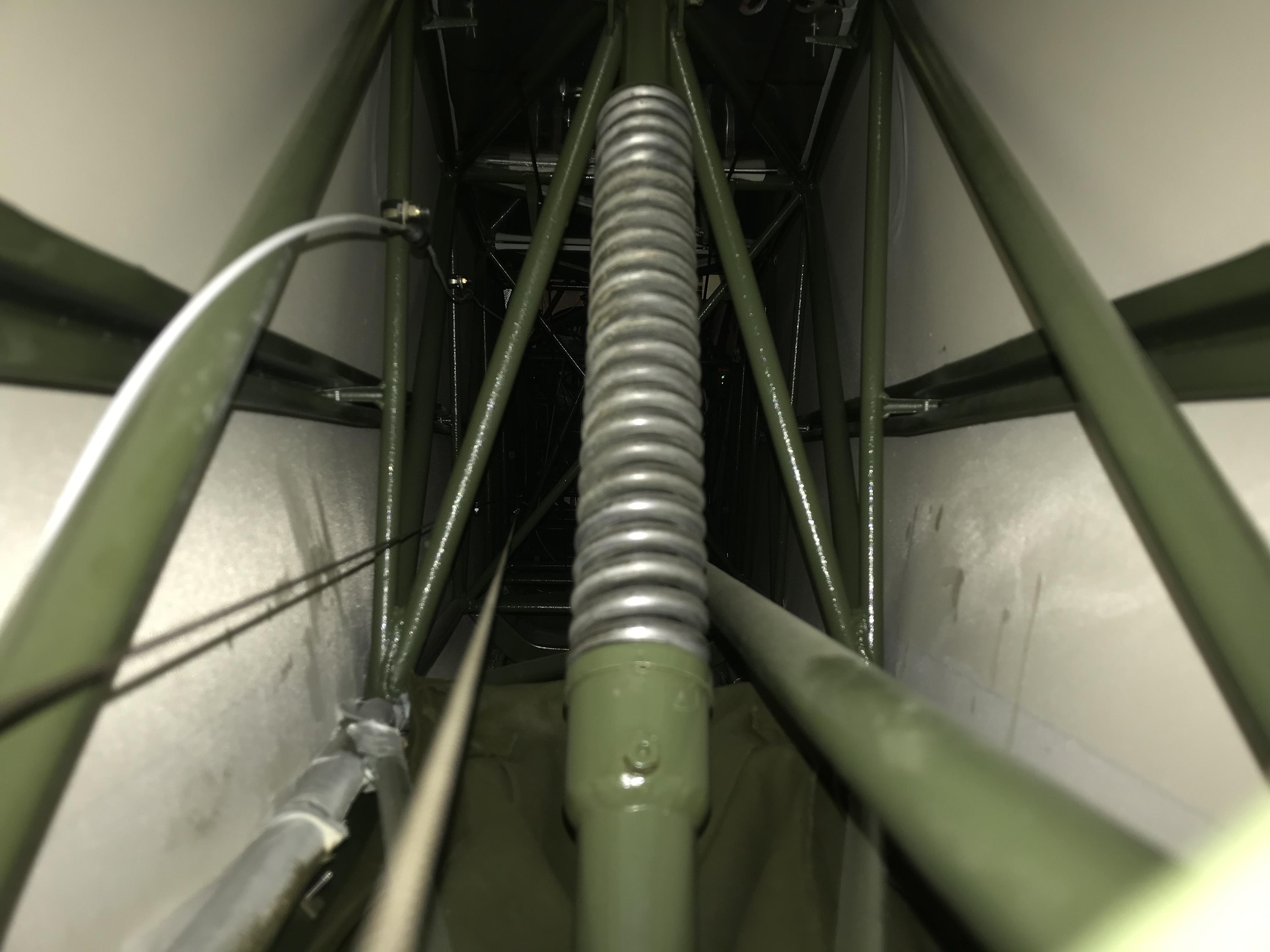
Looking at 76-42011 the strut spring length is 11.62 inches and there are 24.5 coils. So my strut spring length is good. Here is a photo of the strut spring in its non compressed state.
-
2022-01-30 at 7:20 pm #5007
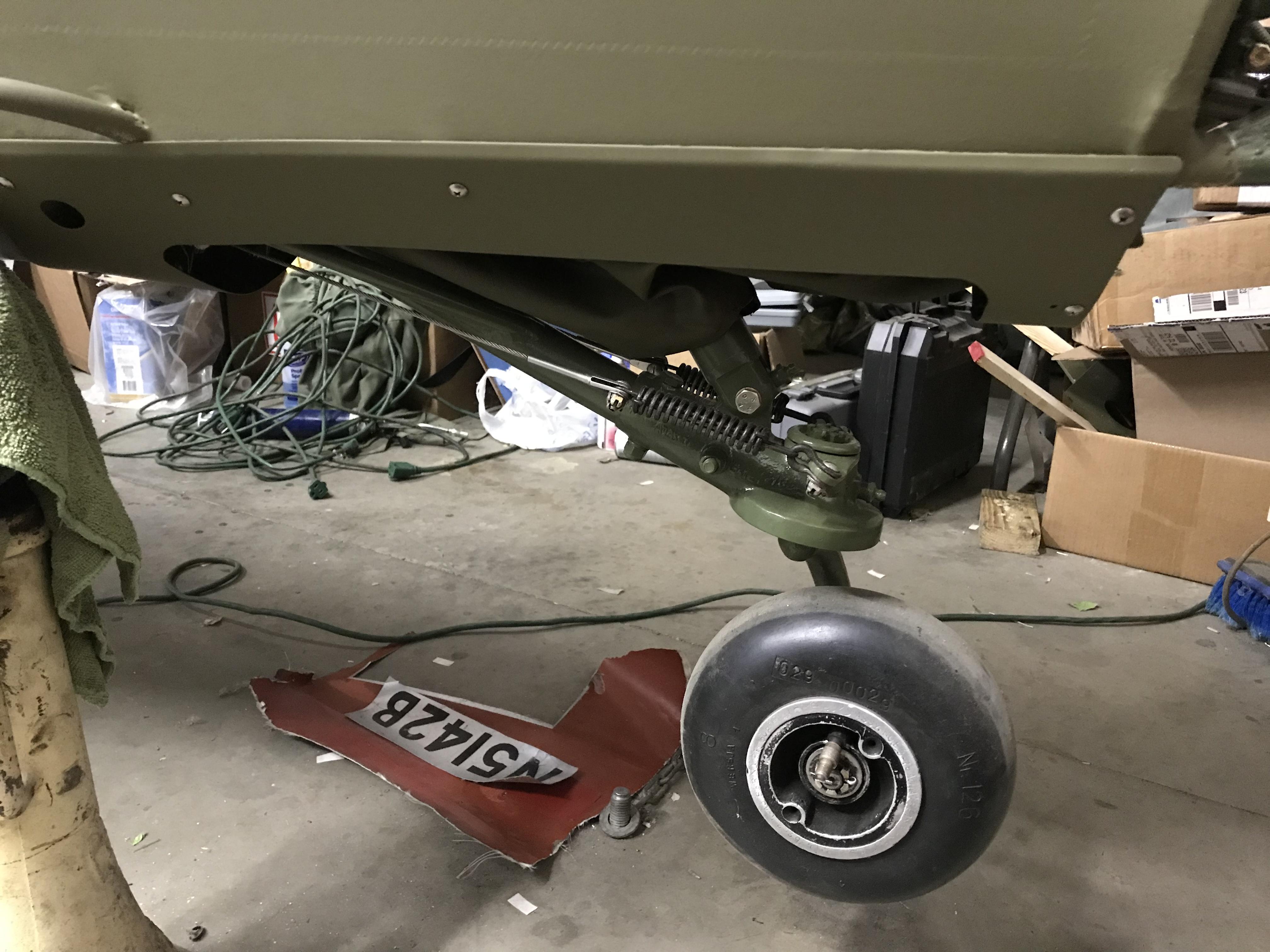
Here is the tail wheel off the ground. Note that the tail drop, it stays at the uncompressed strut spring length as shown in previous photo.
-
2022-01-30 at 7:23 pm #5008
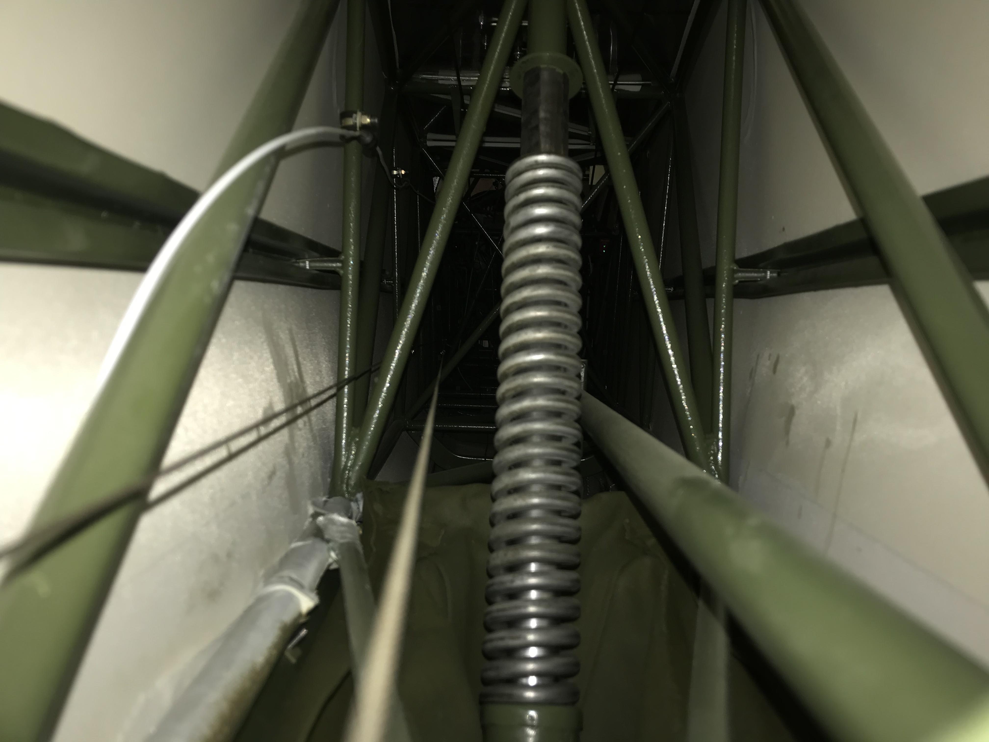
If I push the tail wheel down, I can get the strut to extend past the length of the spring. Note extra space above spring.
-
2022-01-30 at 7:28 pm #5009
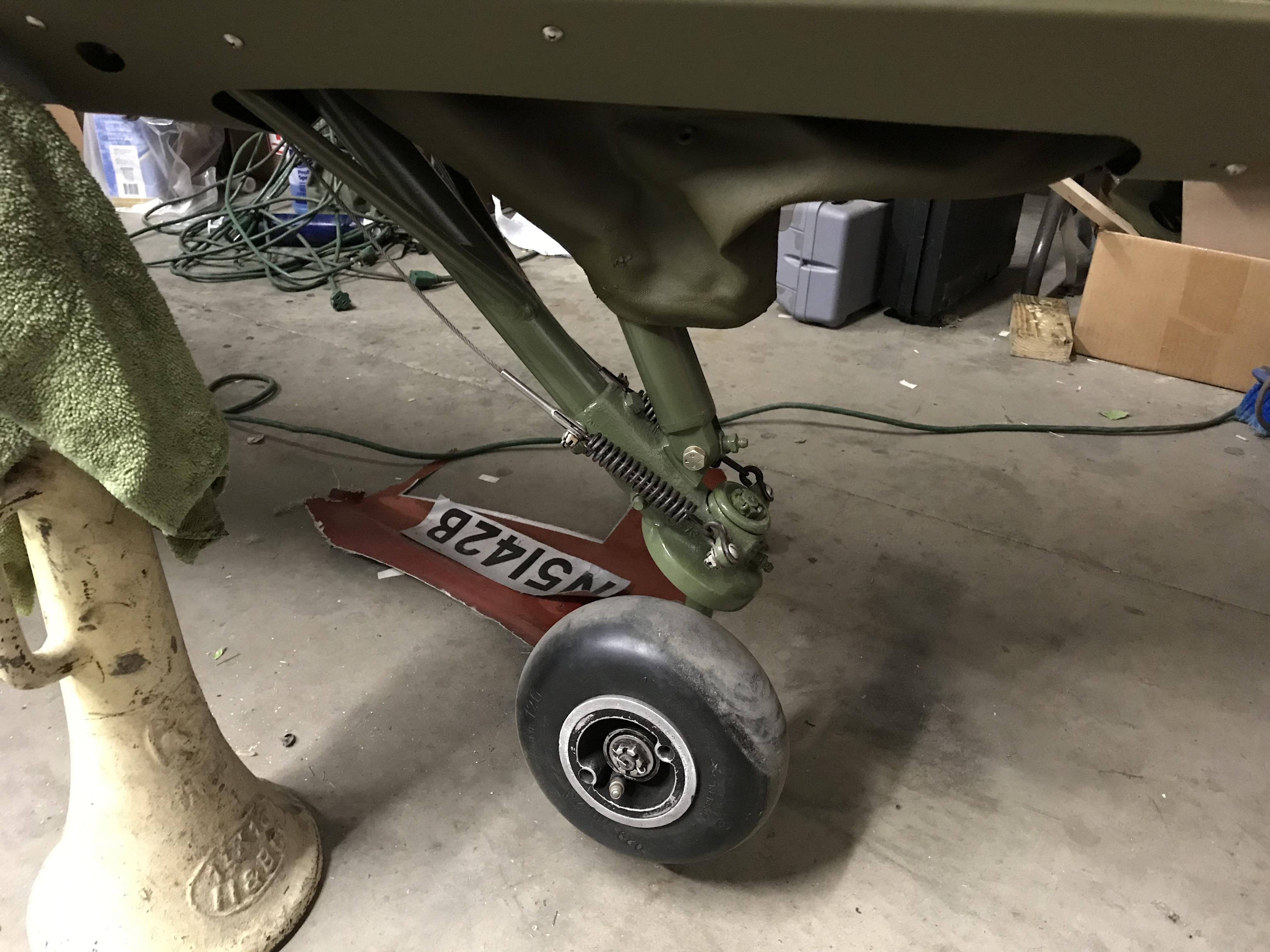
Here is the tail wheel after I pushed the tail wheel down. With the tail wheel in this position and suspended above ground, I tensioned up the tail wheel cables evenly measuring turn buckle lengths until I got 10# tension then evenly backed them off until it returned to 0# to ensure all extra slack was removed. Then safetied.
-
2022-01-30 at 7:33 pm #5010
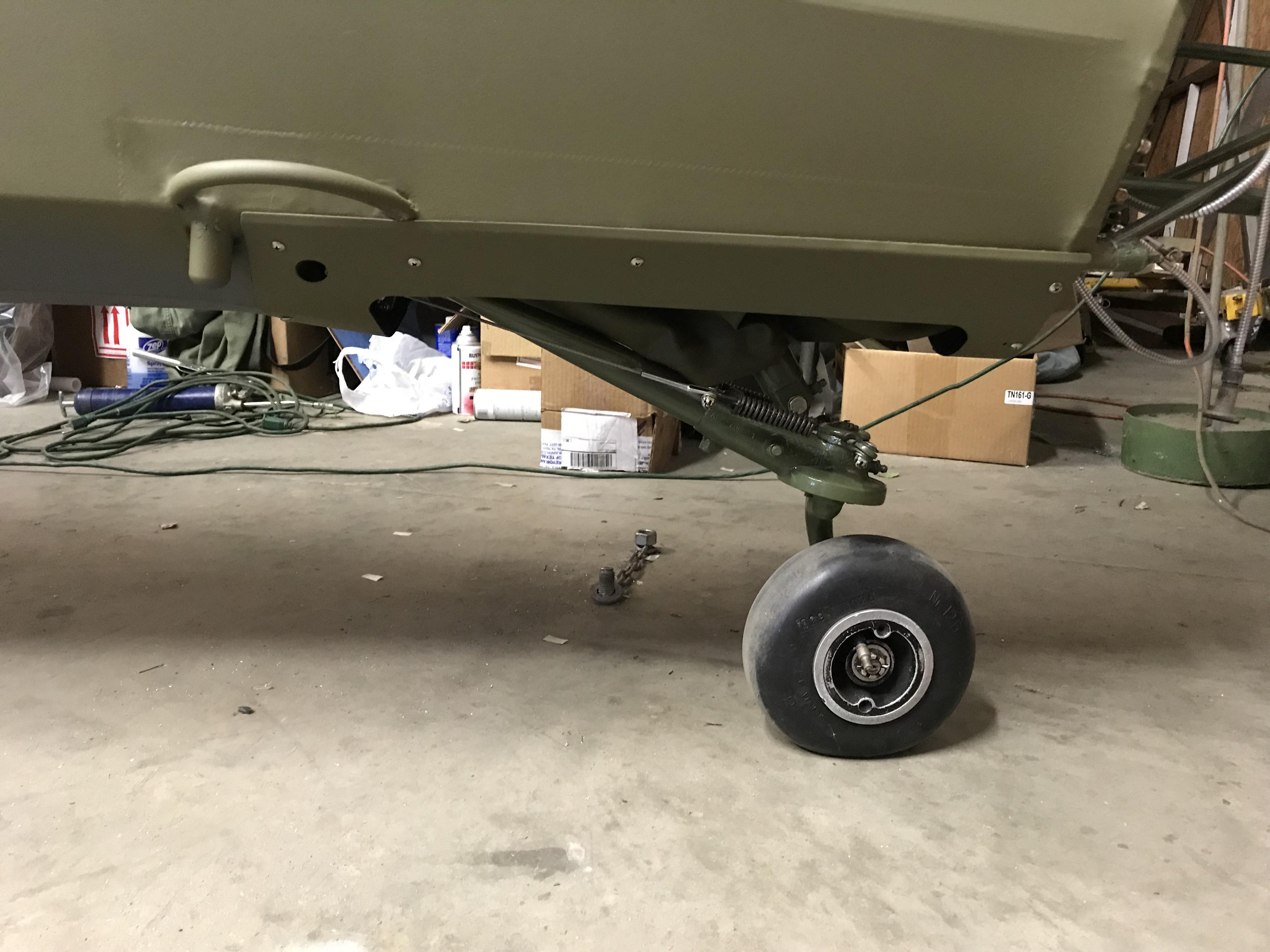
Final photo to show tail wheel resting back on the ground after all rigging complete. Out of curiosity I measured the tension on the tail wheel cables with tail wheel back on the ground and they measured 30# which I believe sounds reasonable. Will not know for certain until taxi test.
-
-
AuthorPosts


- You must be logged in to reply to this topic.