Forum Replies Created
-
AuthorPosts
-
Cheers Jim,
Frank is looking promising atm, will keep you informed.
Hilly
Many thanks to you all Don, Charles & Jim.
Your advice is GOLD and I have passed it all onto Alpine Aviation. I am sure they already know this but now they have your advice as well, so as they say in the classics “Belts & Braces”.
Hilly
Many thanks for the advice Charles, I will be sure to pass that on.
Hilly
G’day Don,
Many thanks for such a quick response and for your advice, your link worked by the way. Quick as you are mate, you have been beaten to the punch, Sam Taber has come to the rescue.
FYI, as it happens the valve removed from my L-5 was an E-1 and as I said to Sam ‘I didn’t know there was a difference’, still, I am more than happy to refit the F-1 and will look for an appropriate dial for the F-1.
Many thanks once again.
Hilly
G’day Craig,
Many thankls for your kind assistance and I do hope you are safe and well. I hope you have been discharged well from your hospital stay. As an observation; for my working life, my office has been an example of what an office should look like but I think at my stage of life it is now allowed to look like….. Beirut!!
I didn’t realise you had an L-5B, your shelf looks metal in the IPC diagram and of course, no drawing in the AirCorps library.
I have been using both drawings you refer to. You may note that while 72043 refers to shelf 72033 and shows the original shelf design which differs from 72033 drawing. The phenolic block supports the ply (underthe shelf) that has been bent down. Figure 63 of the IPC shows the same self. The instruction on 72033 drawing is to dril 4 x holes to match the crystal holder in drawing 72012 which of course does not exist (at least in the AirCorps library).
Many thanks for you guidance and kind assistance Craig. Might have to John Wayne this one!! (shoot from the hip)
Stay safe and well mate.
Hilly
G’day Craig, can I ask a favour please mate?
Do you have any photos of your crystal holder mounted to power supply shelf?
I reacon I know how its all mounted up but the drawings (including the dia in the IPC) are not clear. I plan to use four countersunk screws from the holder throught the mounting brackets on the shelf.
I can’t believe how such a simple operation is so easily sent down the rabbit hole. I am sure a couple of photos will clear it up and allow me to sign it off.
If you have some photos, please use my email: grhilly@ozemail.com.au
Hilly
Many thanks for all the advice gents, the shelf has been completed and final fit today before it heads off to the paint shop and the crystal holder to be made next week.
I followed Charles lead and recently recieved 20 from Yesteryear Aviation, many thanks for the heads up Charles, I found Dave Groh very helpful. He is not so good with online requests but excellent and responds quickly to phone calls. Dave has plenty in stock if you are still looking but they are expensive (USD$3 each plus any shipping). Glad i got some before the latest exchange rate fiasco.
Many thanks Craig, thats great news. Those measurements are really helpful.
I will pass on your info to the maintenance Engineers and order the micarta. We have the drawings for the canvass cover so no heartache there, that has been ordered from our upholsterer.
Hilly
Many thanks Craig, been a while but progress has been made.
The steam bending has gone well and the shelf with stiffners and brackets has now been built. Just the crystal holder and cover to be cut and added and job done. Have radio tech following up on your recommended crystals, so they won’t be far away as well I guess.
For the holder (76-72012) itself, it looks pretty simple to make and fit, but I cannot locate any drawings for it so not sure of dimensions and material specs. Is it ply wood, metal or phenolic material and are you aware of the dimensions? If not and as nothing else seems to fit a drawing, we will probably just “eye ball” it anyway. I mean, how hard can it be, right??
Hilly
Many thanks for your kind assistance, wise advice and guidance Craig.
If I may ask one more favour from you please: can you email the image of the battery specs to me (can’t copy, transfer or print from this platform). Please use: grhilly@ozemail.com.au
Jim, happy to provide a bouquet for the missus and if you want the deed to any farm I own, then it’s yours (no farms here mate….that I know of). I will file away the obscure information as you have enlightened us , all good info and part of the learning mate.
To you both, I am grateful for the time you have taken and guidance provided and I have enjoiyed this discussion. All of this, I think, should be shared with others as well.
Both of you have so much information filed away in your heads I wonder if there is an opportunity to share with other L-5 owners & operators separated by the tyranny of distance. Maybe via webinars, blogs, vlogs, youtubes or any other modern electronic means. Maybe we can have a regular online vidcons and include a scripted lesson.
I have looked back over this conversation and think about the time and effort we have put in. As they say in the classics: there is no tone or intent in short messaging and it’;s so time consuming. Some of your really good information & lessons can be delivered with so much more power and purpose.
If all else fails I prefer a phone call or online video messenging.
Many thanks guys.
Hilly
Geez Jim, now I feel so thick!! You will have to help me out here mate, while I guess the quality of some of the drawings is pretty ordinary. when I look at some of the drawings they say L-5 not L5G.
All that said, there is still so much I have to learn.
So, is there any information for battery installations post these drawings, particularly the AN3152?
Cool Craig,
When I look at the AirCorps library drawings I find 76-64003 BOX – BATTERY EXIDE 12 VOLT with internal dimensions of 10 7/16″ long x 5 7/16″ wide and 12″ high which has a lid. Dimensions from your mate are pretty close.
There is also a drawing 76-64303 SHELF – BATTERY which seems pretty basic and has holes to match 76-35038 SHELF ASSEM – BATTERY. The dimenions look a bit odd to my eyes in that it is too short and too wide for a neat fit of the battery box. That said I could be reading the drawings incorrectly.
Finally drawings 76-64304 BATTERY HOLD DOWN STUDS (which look like a simple rod threaded at both ends), 76-64336 TUBE – BATTERY INTAKE and 76-64339 TUBE – BATTERY DRAIN (self-explanatory).
When I compare the photo kindly provided by JG, I wonder if the L-5 & L-5B installations were different. Only drawings for a single install so not sure that is right either.
Many thanks for your help Craig, next time I am at the aircraft -maybe a month or so – I will take to the current mount to measure and compare.
G’day Graig & Jim,
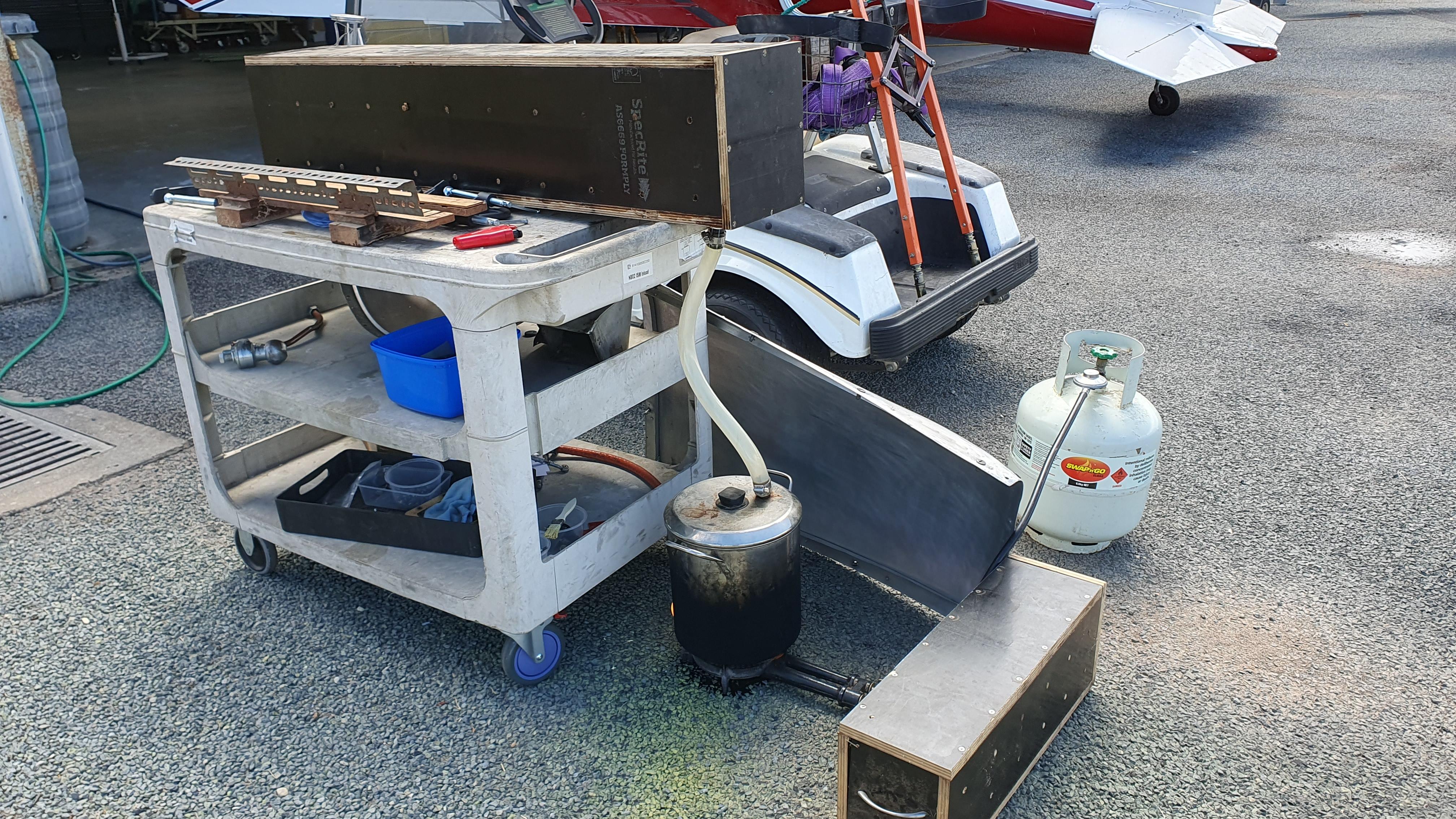
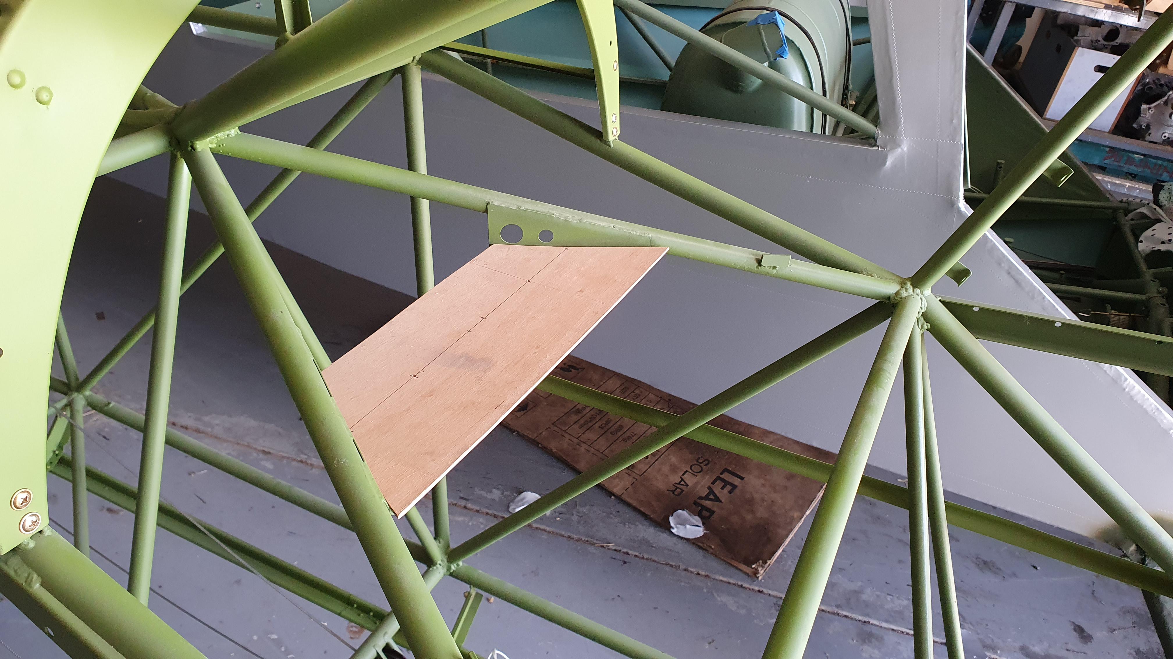
Many thanks for your info Jim, exactly what we thought but didn’t know. We are currently in the throws of steam bending (see below) & laminating the rib brackets for our “sh1ttee wing” so that makes life really easy. We will make a couple more.
Thats good information too Craig, I will pass that onto the team and confirm what we are going to do for the crystals. we had simply planned to drill to the same hole dimensions as the radio. I only have access to one crystal atm and it’s with the radio tech in Melbourne, so I will follow that up. At half a pound per crystal makes it a very heavy load for such a light structure. The radio will prob never get used in anger so a pastiche may the way forward. Sage advice Craig, thank you.
Our steamer with former template:
Also taken the decision that we cannot make it to the US this year, too many priorities and too few resources. I think the world is all in the same boat by the sounds of it.
As they call in HHH: On! On!
Hilly
-
AuthorPosts