
Forum Replies Created
-
AuthorPosts
-
Try Frank Boermans (frankboermans@gmail.com) in Europe. He might have some slats that came with a pile of Italian spare parts he bought with his flyer. Good luck.
Do not attempt to turn an NOS valve out-of-the-box until it has been disassembled, the cork seal (a cone) has been re-hydrated, and the valve reassembled with “EZ Turn” or a similar synthetic lubricant that is unaffected by fuel or solvents and meets Mil-Spec Mil-G-6032D. Likewise, a fuel valve on any flying L-5 that is difficult to turn should receive the same treatment. One unnecessary fuel starvation accident that occurred around 15 years ago was attributed to an F-1 valve that wouldn’t turn freely.
Also, watch for swelling of the cork seal at the fuel ports. Any amount of distortion of the surface can cause the cork to be torn by the sharp edges of the ports, thereby rendering it useless. It would also be wise to polish the internal edges of the fuel ports if there is any roughness to them.
In our experience (me, Sam, Duncan, and many others), 2 out of 3 NOS valves have interior corrosion or other defects from improper storage over the last 60-80 years since manufacture. If possible, get a refund or replacement guarantee from the seller. Twenty years ago, when you could by buy them by the dozen for $25-$35 each, that didn’t matter so much.
JG
Do not attempt to turn an NOS valve out-of-the-box until it has been disassembled,the cork seal (a cone) has been re-hydrated, and the valve reassembled with “EZ Turn” or a similar synthetic lubricant that is unaffected by fuel or solvents and meets Mil-Spec Mil-G-6032D.
Also, watch for swelling of the cork seal at the fuel ports. Any amount of distortion of the surface can cause the cork to be torn by the sharp edges of the ports, thereby rendering it useless. It would also be wise to polish the internal edges of the fuel ports if there is any roughness to them.
In our experience (me, Sam, Duncan, and many others), 2 out of 3 NOS valves have some interior corrosion or other defects from improper storage over the last 60-80 years since manufacture. If possible, get a refund or replacement guarantee from the seller.
Sean Ayres 805-757-1709
If you still have trouble his dad Don is 42.sentinel@comcast.net
Of course I do. Besides you…
Phil Nash (AK), basket case w/ casein wings
Ron & Stuart Lee (Australia), under restoration
Chris Bergen (CA), restored, not currently flying
Mike Long (Australia), flying
Darren Crouser (TX), flying
Pima Air Museum (AZ), display only, not airworthy
Duncan Cameron (NV), from India, resto. pending
Diego Trevisan (Italy), flying
Ed Soderbloom (WA), flying
RNAF Museum (Netherlands), flying
Bill Barclay (CO), flying
Ron Fagen (MN), flying
CAF Joe Foss (SD), flying
I-AEGB (Italy) Restored in 90’s by Italo Battioli, current owner and status unknownThere is supposedly one at a museum in Beijing, but the s/n is unverified. Ron & Stuart Lee own another B-model (VH-CRO) but it was severely damaged by the previous owner in a flying accident and repair is doubtful.
Thanks, Craig, good work. I can’t believe the prices being asked. I bought two or three of the phenolic ones around 2005 for $15 each, and $10 for a bare aluminum one. Can’t even buy single switches for that little now. Aero Antique probably has the best price now at $75.
I’d guess you’re aware, but in case you’re not, from the C-model onward the recognition lights were mounted on an aluminum panel that also incorporated the camera aperture. p/n 76-76012.
That’s my sketch of the panel, done many, many years ago. Without access to the proper tooling, the hardest part is making the mounting rings and doing it cleanly. Don Ayres made some beautiful repros of the panel assembly with rings, but it was a limited run of maybe 5 and I was very lucky to get one of them.
The aluminum 42D-5051 control switch boxes were used up to at least 42-99467 (photo evidence). I haven’t been able to pinpoint where it was replaced by the later Bakelite version, but it may have been used throughout the entire “observer” series. Some of the earliest boxes were bare aluminum, not black, by the way (again, photo evidence).
The E and G series definitely had the later style and maybe the B and C too. I’ll do some digging unless you know for sure. The parts manual doesn’t differentiate between the two, that I can see (same AAF part number). The G used 28-volt bulbs, of course.
As I’ve written to you before Geoff, an original example of the crystal holder had incorrect hole spacing and the crystals didn’t fit!
Craig,
The FAA Engineering Office (ACO) in Chicago has a small staff and they aren’t set up to handle visitors who do research. They have no copying equipment for visitor use and nothing can be taken off-site for professional copying, although they did photocopy some reports for me on one of their copiers (I don’t recall the fee). Any equipment brought to their office other than a small flatbed scanner or camera must be approved beforehand, and everything entering and leaving the building is screened by security.
Because very little would fit on my 10×14 “legal size” scanner, I photographed most items instead. Given the age and fragility of the heavily-creased drawings larger than ANSI ‘A’ size, it was impossible to flatten them without risking damage. According to my archivist-wife, the only practical way to handle and copy them properly would require a lot of time for controlled humidification of the paper (allowing the creases to relax) and some very expensive ($50k+) large format scanning equipment.
To accommodate us during our visit, the ACO staff cleared off a desk in a dingy 12′ x 20′ basement storage room that was piled with boxes and broken / unused equipment, so there wasn’t much room to work. They did make a conference room with large tables available to us for most of one day so that we had room to unfold the large drawings, but we were required to have an escort to walk between the rooms on separate floors, which was inconvenient for us and the ACO staff.
All of the records are warehoused off-site, so getting the boxes ordered took time and needed coordination with our schedule and their schedule. Because the files weren’t very well indexed, I had them pull something like 20 file boxes containing “orphan-status” Stinson material to be sure that I had covered everything date-wise from 1940 onward. Only six of the boxes held pertinent information, (which I thoroughly indexed for the ACO to aid future researchers) but it was better to cast a wide net to be sure that we didn’t miss anything.
Although it should be obvious, I should mention that there is no public access to currently supported TC and STC engineering data, no matter how old it is. There is no statute of limitations on proprietary aircraft design and engineering information, so before honoring any request for a research visit the ACO has to go through the time-consuming process of determining whether the type certificate holder of record still exists or has sold/transferred the rights to a new owner. That alone can take months if it hasn’t already been established, and in my case back in 2012, it took over a year because no one had previously requested engineering data and drawings for the L-5. Unless the ACO has formally declared which aircraft are “orphans” since that time, you can probably expect a similar delay with whatever “20’s/30’s” aircraft it is that you are referring to.
Good luck,
JG
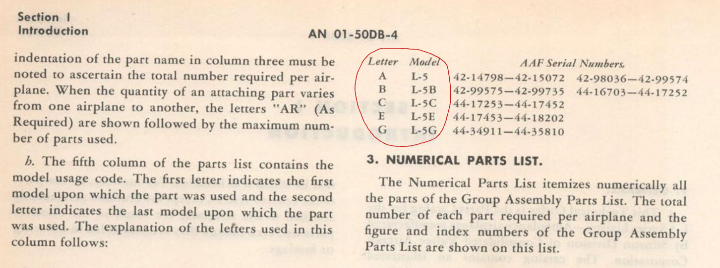
Correction Craig: There wasn’t an “A model”. Although the “observer” model is often referred to as the L-5A, that was not an official designation. In addition to what can be derived from the maintenance manuals, I have thousands of pages of Wright Field documentation on the L-5 program and it provides incontrovertible proof that the L-5A never existed, despite what commercial publications such as Jane’s All the Worlds Aircraft have published for the past 70 years. It was designated as an L-5 throughout production until the L-5B ambulance version was introduced. If you look at the chart below from the Introduction section of a late edition of the Parts Catalog, it is quite clear:
-
This reply was modified 2 years, 7 months ago by
admin.
Hilly,
Not only are drawings 64303, 64304, 64336, and 64339 for the L-5G as marked, but so is 35038. Although it says “L-5” in the title block, it should say L-5G instead. Being intimately familiar with that model because I own one that is disassembled, used to own the frame of another, and have laid eyes on several more, I instantly recognized that this is the assembly welded to the fuselage tubing at the firewall, where the 24-volt battery is located. On all of the 12-volt models, the battery shelf located behind the front seat has different dimensions and has different support tubing associated with it.
A few details in that blueprint are also clues that it is a late-model part. The title block indicates that the drawing was created on 2 March 1945 and was approved by the Chief Engineer and Project Engineer on April 4, and the note next to the title block says that 76-35038 replaces 76-31164. Even though the drawing for the earlier part isn’t in the blueprint set, it can only have been the earlier welded battery shelf assembly used on the 12-volt airplanes, especially because the L-5E series started rolling off the assembly line in February 1945 before the drawing 35038 was made.
That isn’t a fact generally known, however, so I have an advantage over you and most other L-5 enthusiasts there, but the clincher is that the “Model No” referred to in the title block is CS-91 which is an engineering reference to the ‘G’ model. Like serial number 9001 being the Model 76 prototype for the L-5, this extremely obscure bit of trivia isn’t something that I would expect anyone else to know, and I only sussed it after poring over hundreds of drawings and stumbling across a few that spell it out plainly. Anyway, while I have looked at it many times before, until now I never noticed “L-5” or “CS-91” on drawing 76-35038 because it was already plain to me that it is the G-model battery shelf and I had no reason to look deeper until you posted your question about it.
To answer your other question about AN3152 and any other drawings concerning battery installation, there aren’t any in the NASM blueprint set that we can refer to because most of the superseded drawings were deleted. However, back in 2013, I filed a Freedom of Information Act request with the FAA to gain access to their engineering data and in 2014 had the rare privilege of rummaging through their collection of L-5 documentation for three days. This included several boxes stuffed with original blueprints that probably hadn’t been touched since 1946, and among the collection were many “missing” drawings of superseded parts. Duncan Cameron went along on this expedition and here is a photo of him holding the first drawing that we randomly selected from the box. His grin says it all – jackpot!
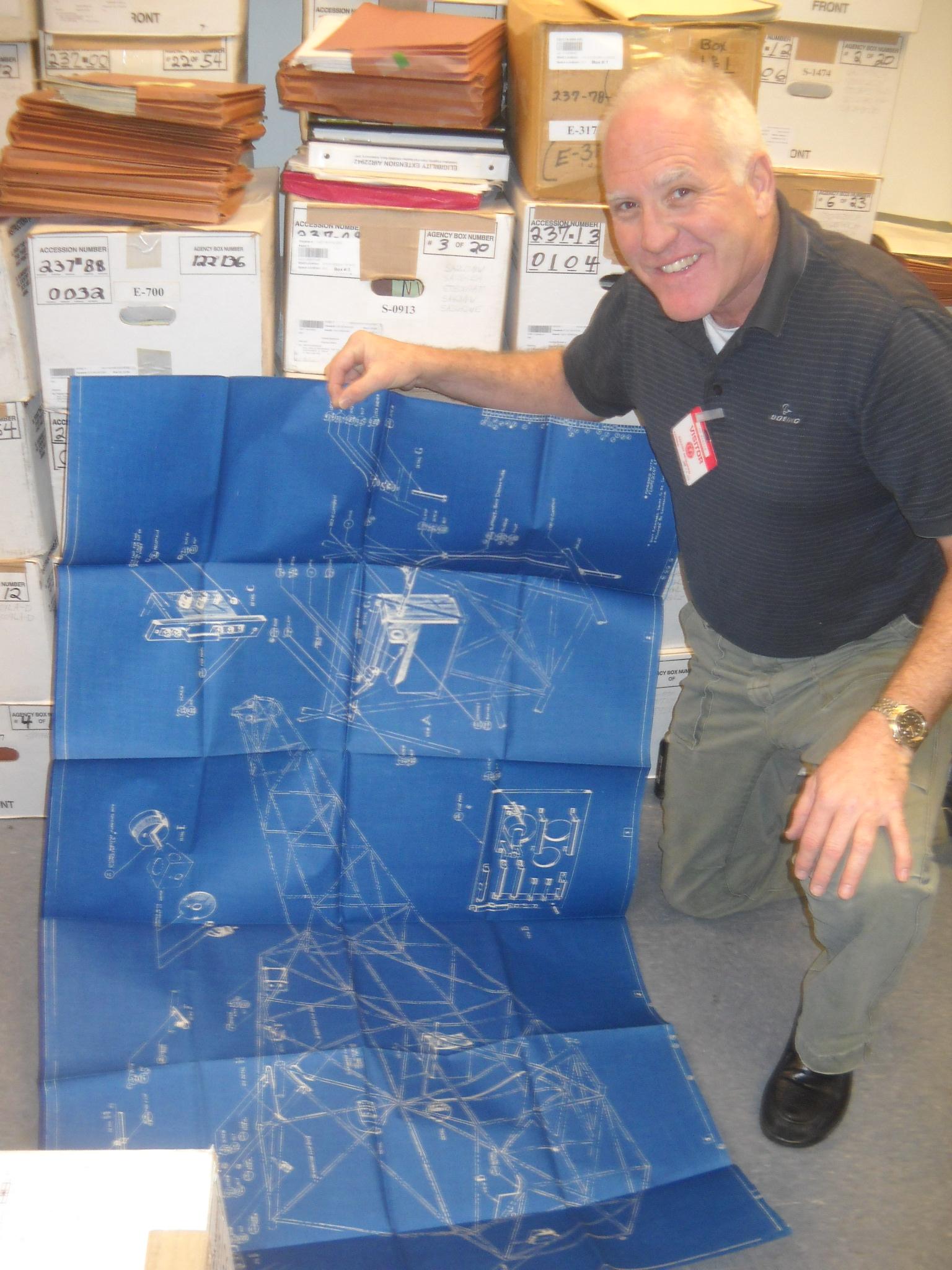
Unfortunately, we found no other drawings concerning battery installation, but this one has some very useful details on it. It is actually for the early L-5, the so-called O-62 batch of planes numbered 76-1 to 76-275, but most items are the same as on later models except for the radio equipment, some of the wiring harness details, and a bit of the bracketry. A smaller version of this blueprint is also probably included in one of the many versions of the L-5 parts catalog, but my set of those is not accessible at the moment, and none of the manuals on the ACA website have it.
My copy of the drawing shown in the photo has been lost, unfortunately so I’ll have to ask Dunc to send me his copy which I will forward to you if you provide two bars of platinum bullion, a bouquet for my wife, and the deed to your farm in Oz (hahaha).
Cheers,
JG
Hilly … look closer at the title blocks of those drawings. 76-64003 is for aircraft 9001 which was NX27772, the L-5 prototype. To my knowledge, that battery box was not used on any production aircraft. All of the other drawings pertain to the 24-volt L-5G (76-3477 & up). The devil is in the details, as they say. A large number of drawings in the set (which are available FREE to level 3 and 4 SOPA members) are prototype or experimental designs only and do not pertain to doing an authentic restoration on any of the production airplanes.
The angles and stiffeners (S-806-x) are bent plywood, the same as the rib attachment angles in the wings and empennage. The best method to fabricate them is to pre-bend individual layers of veneer and then laminate them together using a cold-molding process. That is the only effective way to reliably get radiused, 90-degree bends.
Craig, I believed that Taylor used one of those batteries as a battery box for his G-model if you want to eyeball one in person. One of the reasons they make such a good battery box is the built in venting and drain.
-
This reply was modified 2 years, 7 months ago by
-
AuthorPosts
